

Intro
I was recently thinking about some work I did early on in my career on clocks and synchronisation. This was on a project where we were replacing some circuit switched transmission lines (E1s for those who are familiar) with packet switched technology. In order to do this we were emulating these E1 lines over the underlying Ethernet technology (using SAToP pseudo-wires).
Telecom networks require very precise synchronisation, that is the elements in the network all need a clock which beats at the same time so that as they generate streams of data or broadcast on particular radio frequencies they are all aligned. These clocks beat many millions of times per second, and so keeping them synchronised is not a trivial task.
One good property of E1 links is that their typical physical transmission layer (HDB3 - high density bipolar 3) allows clock recovery without a separate clocking line. This is not possible when using something like Ethernet though, this has no physical layer synchronisation and so you have to use packet based synchronisation approaches like NTP or IEEE1588v2.
As part of my work, I was testing the quality of the clocks recovered from these packet technologies and comparing it to a reference to see if we could successfully use it and we were using various (and expensive) pieces of technology to do this.
So that brings me back to this post… I’ve been doing a bit of work with my new favourite microcontroller recently, the Raspberry Pi RP2040, and I decided to see if I can build an instrument to test clock quality based on this microcontroller.
What do I want to measure?
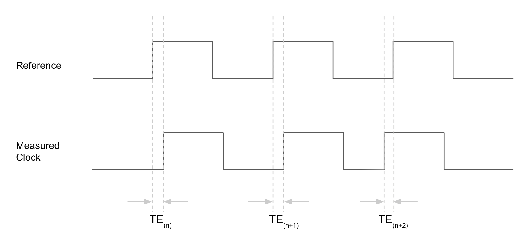
A key quantity we looked at was Time Error (TE) and its derivations, Time Interval Error (TIE) and Maximum Time Interval Error (MTIE).
Time Error (TE) is a measurement of the offset between a measured clock and a reference clock. It is often measured in the time domain, and specified in microseconds (us) or more commonly nanoseconds (ns). A nanosecond is 1 billionth of a second, but this resolution is necessary when we are talking about clocks with frequencies in the MHz (millions of cycles per second).
TIE is a measurement of the change in TE over a given observation window, typically specified in seconds. It is the accumulation of error (TE) in that window.
MTIE measures the maximum TIE value for a given interval across an entire set of measurements taken. For example if we ran a test for 100 seconds we’d calculate the 5 second MTIE by looking at all the windows of 5 seconds across the 100 second test and finding the TIE for each and then taking the maximum of all those values.
Given all this though, the only thing we need to measure at the electronic level is the phase offset between the leading edges of the reference and measured clocks.
Where I'm starting
I’ve decided to start off building a simple frequency counter and then move to something which can measure the offset between two clocks. This post covers how that frequency counter works as I had a few goes at building it.
First an overview of the RP2040 microprocessor:
- 2 ARM Cortex M0+ cores running at up to 133MHz
- 264KB SRAM
- 16 PWM channels (8 which can be inputs)
- 4 programmable I/O (PIO) state-machines in 2 blocks
- Hardware support for USB 1.1, UART, SPI and I2C
It is a very capable microcontroller, and the PWM and PIO features are very useful for building a frequency counter.
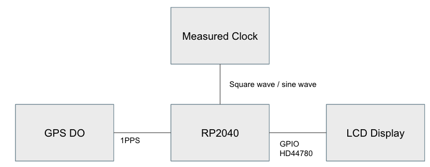
My design concept is to use a reliable 1PPS output from a GPS and to count the number of pulses from the measured clock between each of these pulses. The 1PPS can use an interrupt to take a snapshot of the measured clock pulse count, this gives us the number of cycles (pulses) per second.
Implmentation approaches
There are three broad approaches to implement such a counter with the RP2040. Let’s look are pulse counting first, we can do this in three ways:
- Interrupts
- Using a Pulse Width Modulation (PWM) counter
- Using PIO
I ruled out option 1 because interrupts will not be able to keep up with multi MHz signals, so I went straight to option 2, using the PWM counter.
PWM
The PWM block of the RP2040 has 8 slices with 2 channels each (A and B). The B channel can be used as an input, so if there’s a pulsing signal you want to count you can connect it to one of the B pins and it will drive the PWM counter for that slice and channel forward.
uint setup_pwm_counter(uint gpio) {
    // can only use input on channel B
    assert(pwm_gpio_to_channel(gpio) == PWM_CHAN_B);

    uint slice_num = pwm_gpio_to_slice_num(gpio);
    pwm_config cfg = pwm_get_default_config();
    pwm_config_set_clkdiv_mode(&cfg, PWM_DIV_B_RISING);
    pwm_config_set_clkdiv(&cfg, 1.f);
    pwm_init(slice_num, &cfg, false);
    gpio_set_function(gpio, GPIO_FUNC_PWM);

    // register interrupt handler
    pwm_clear_irq(slice_num);
    pwm_set_irq_enabled(slice_num, true);
    irq_set_exclusive_handler(PWM_IRQ_WRAP, on_pwm_wrap);
    irq_set_enabled(PWM_IRQ_WRAP, true);

    pwm_set_enabled(slice_num, true);
    return slice_num;
}
This can work up to ½ of the clock speed of the RP2040, which on a Pico (the reference implementation of the processor) is 125MHz, so you can count clocks up to 62.5MHz (note that you can increase the clock speed of an RP2040).
One of the challenges of this method is that the PWM counter is a uint16_t, a short integer which has a maximum value of 65535 - which would be exhausted pretty quickly on a signal whose frequency measures beyond 65kHz, so we need a workaround. Luckily there is an interrupt raised when the PWM counter overflows, so if we keep track of those we can calculate the total number of pulses as the total number of overflows * 65536 + current PWM counter value.
The full code for the PWM version is here: https://github.com/richardjkendall/rp2040-freq-counter/tree/main/pwm
PIO
PIO (or programmable IO) are specialised state machines which run independently of the RP2040 CPU cores and which can perform limited IO based functions. They are very fast, and can communicate with the CPU via FIFO queues, DMA or interrupts.
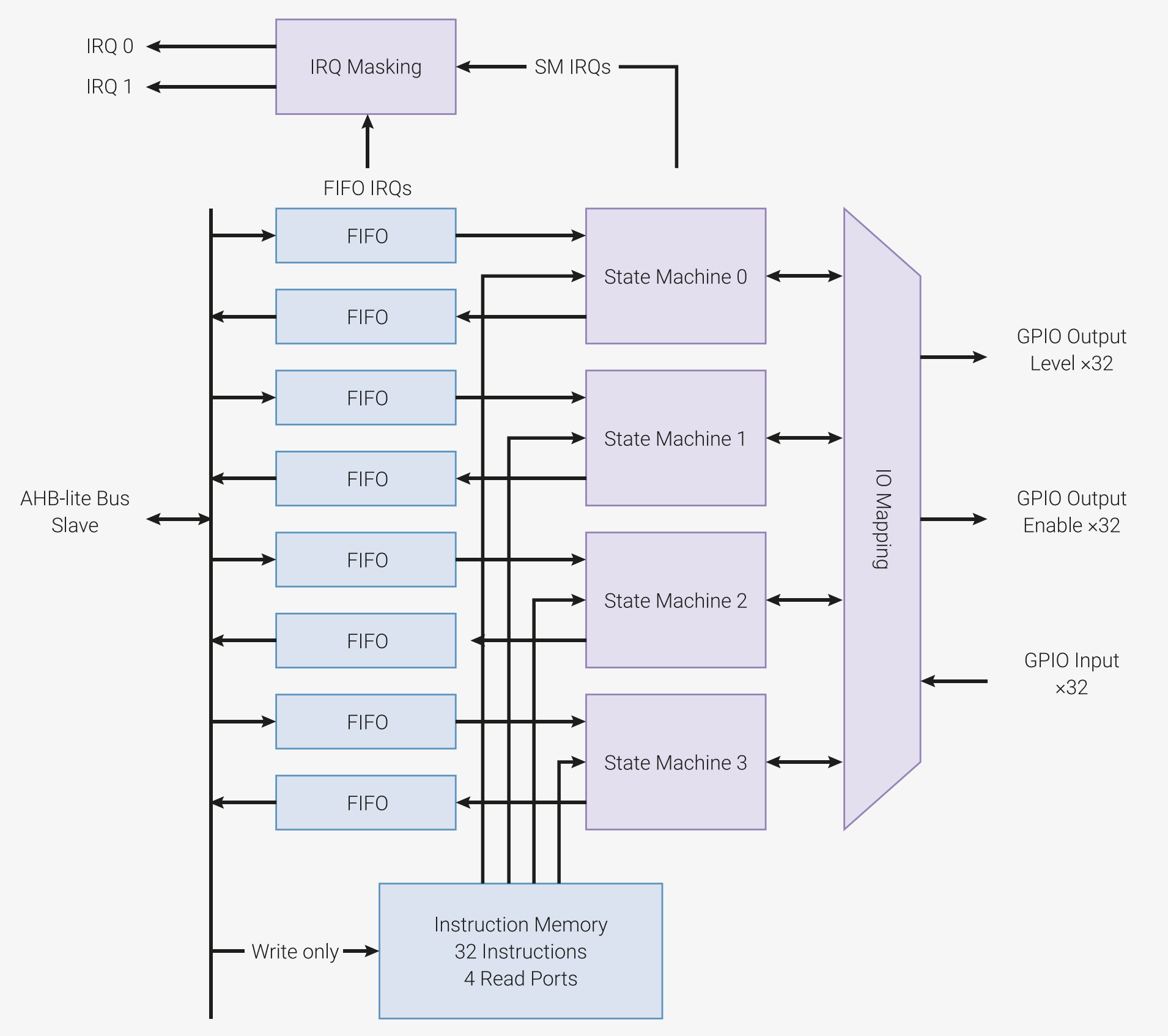
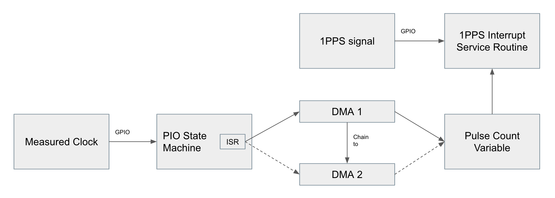
My PIO state machine design is very simple, it waits for the GPIO pin to go high and then decrements a counter (PIO cannot increment). The first version I built used the FIFO queue to send data back to the CPU, but I found this was not reliable for timing (I was missing some pulses) so I switched to using DMA to stream the counter into a single pulseCount variable which can be read by the CPU on each 1PPS interrupt.
.program counter
    mov x !null         ; setup initial value
main:
    wait 0 pin 0        ; wait for low if high
    wait 1 pin 0        ; wait for high
    jmp x-- next        ; decrement counter
next:
    mov isr x           ; put current counter value in ISR
    push noblock        ; push ISR value to CPU
    jmp main            ; go back to the start
I did have to get a bit creative with the DMA solution, because DMA blocks will only run for a given number of cycles and that maximum number is 0xFFFFFFFF or 4,294,967,295, which when you are counting a 10MHz signal will be exhausted in ~430 seconds. There is an option to ‘chain’ one DMA channel to another such that the second channel is started when the first one finishes. You can therefore recursively chain two channels to get a continuous stream of data and this is what I did.
    // setup DMA
    dma_chan = dma_claim_unused_channel(true);
    dma_chan2 = dma_claim_unused_channel(true);

    // channel 1, this starts and than hands over to the second channel when it is done
    // channel 2 then hands back to channel 1, so we get a continous DMA stream to a single target variable
    dma_channel_config dc = dma_channel_get_default_config(dma_chan);
    channel_config_set_transfer_data_size(&dc, DMA_SIZE_32);
    channel_config_set_read_increment(&dc, false);
    channel_config_set_write_increment(&dc, false);
    channel_config_set_chain_to(&dc, dma_chan2);
    channel_config_set_dreq(&dc, pio_get_dreq(pio, sm, false));
    dma_channel_configure(dma_chan, &dc,
        &pulseCount,
        &pio->rxf[sm],
        0xFFFFFFFF,
        true
    );

    // channel 2 as above
    dma_channel_config dc2 = dma_channel_get_default_config(dma_chan2);
    channel_config_set_transfer_data_size(&dc2, DMA_SIZE_32);
    channel_config_set_read_increment(&dc2, false);
    channel_config_set_write_increment(&dc2, false);
    channel_config_set_dreq(&dc2, pio_get_dreq(pio, sm, false));
    channel_config_set_chain_to(&dc2, dma_chan);
    dma_channel_configure(dma_chan2, &dc2,
        &pulseCount,
        &pio->rxf[sm],
        0xFFFFFFFF,
        false
    );
The full code for the first PIO version is here: https://github.com/richardjkendall/rp2040-freq-counter/tree/main/pio
Testing
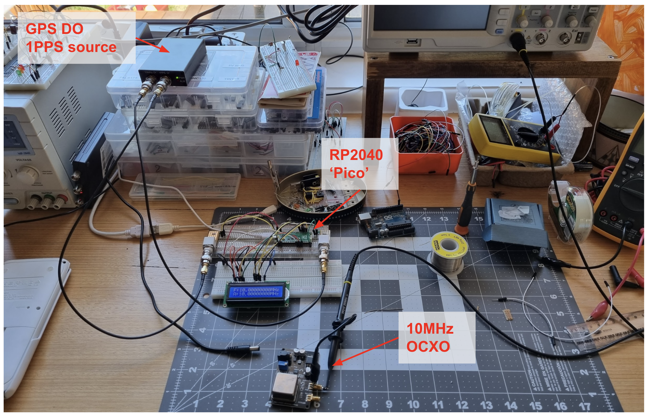
At this point I wanted to compare both of my implementations, so I connected my Raspberry Pi Pico (my test platform for the RP2040) to a GPS disciplined oscillator (DO) with a 1-pulse-per-second (1PPS) output and to a 10MHz oven controlled crystal oscillator (OCXO) running at 10MHz. I let the OCXO warm up for 5 minutes in both cases, and ran the tests for about 1hr each.
Results
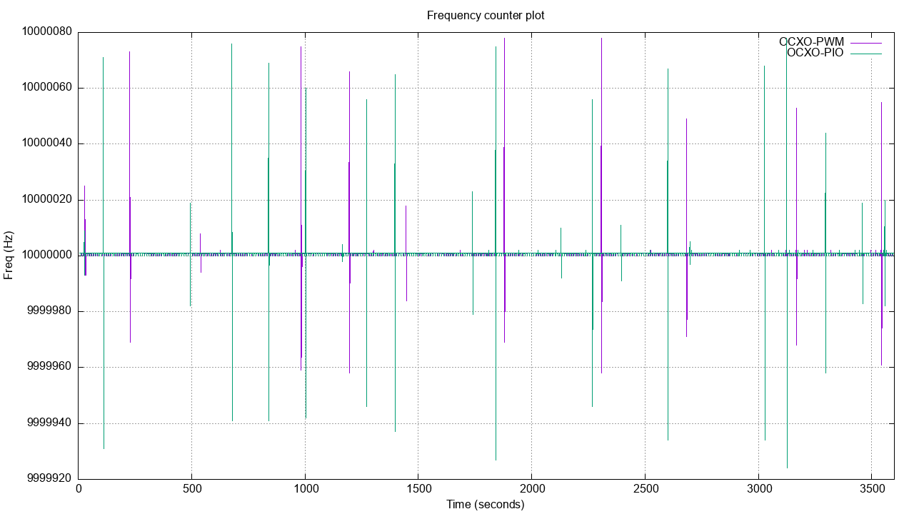
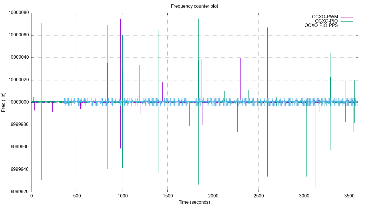
The chart shows that there were some frequent spikes above and below the target frequency, the number of spikes about the same for both the PWM and PIO pulse counting implementations. Looking into those spikes in more detail it seemed as though they were cancelling each other out, with a large spike above the expected frequency followed immediately by a spike less than the expected frequency.
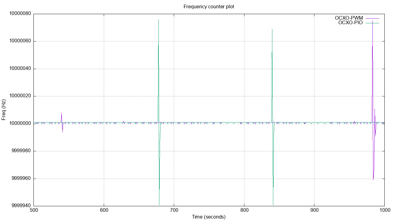
This got me thinking about the 1PPS signal and the interrupt it is triggering. I looked around on the internet and saw some people had done some testing which suggested the time for an interrupt to fire is ~1us, that’s 1 microsecond or 1/1000000 of a second. When measuring something which happens 10 million times per second, this is much too big of a margin, so I decided to see if I could improve on it.
Using PIO for 1PPS
I wanted to see if I could use PIO to shorten the time between the 1PPS rising edge being detected and the pulse count snapshot being taken. The PIO state machines execute one instruction every clock cycle, so theoretically we can reduce the time between the rising edge being detected and action being taken to 8x10⁻⁹ seconds or 8ns (at a clock speed of 125MHz).
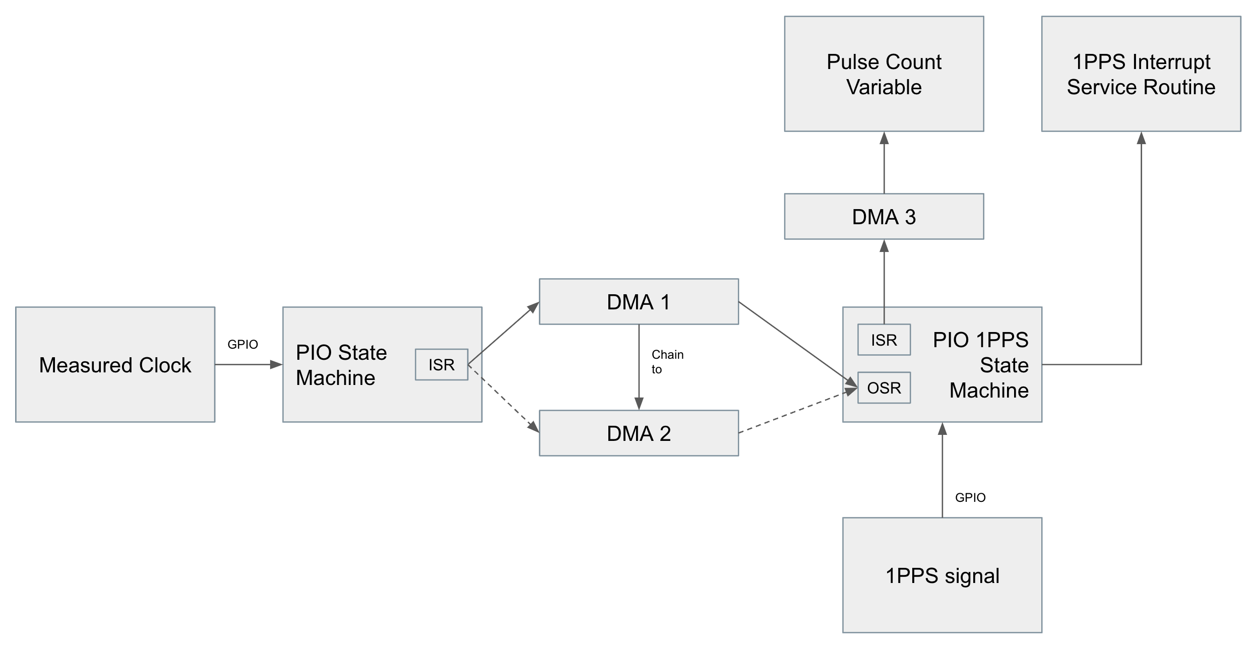
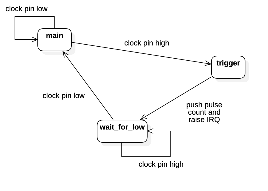
My approach was to have the original pulse counting PIO state machine continue, but instead use the DMA channels to push the pulse count into the FIFO input register of another state machine. This second state machine waits for the 1PPS pulse and when it sees it, pushes the latest pulse count back to the CPU and raises an IRQ which the CPU responds to process the latest data.
.program pps
main:
    pull noblock        ; get inbound data if it is there
    jmp pin trigger     ; jump to trigger if signal pin is high
    jmp main            ; go back round the loop as pin is low
trigger:
    mov isr osr         ; move value from OSR (which is the pulse count sent from the other SM via DMA)
    push noblock        ; push ISR to CPU
    irq set 0           ; set IRQ so CPU can handle the PPS
wait_for_low:
    pull noblock            ; pull again if inbound data is there
    jmp pin wait_for_low    ; if pin is still high then keep waiting to go low
    jmp main                ; pin is low, we start again
I wrote the PIO code to run at the same rate as the pulse counting state machine so that there are no issues with data backing up on the DMA channel between the two state machines. I did this because the DMA channel between the two state machines needs to be paced based on the slower of the two machines.
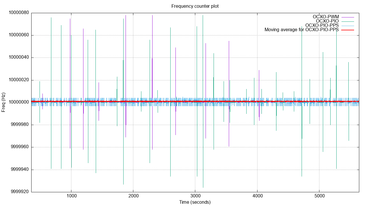
The results of this code are much better than the implementations which used normal interrupts for the 1PPS signal:
Adding a 10-second moving average shows the result over 10 seconds is very close to 10MHz:
The final set of code is here: https://github.com/richardjkendall/rp2040-freq-counter/tree/main/pio-pps
Displaying the results
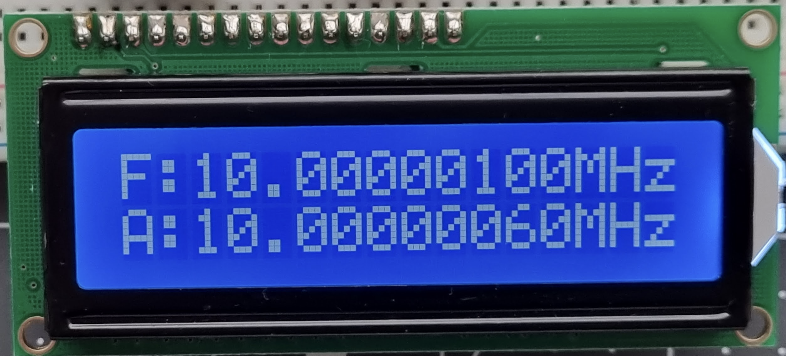
The code writes the output to the serial port (using printf) so it can be logged, and it also writes to a simple 16x2 LCD display. The display output shows the current instantaneous frequency value as well as an average of the last 10 readings.
The display is based on the very common Hitachi HD44780 controller, which implements a simple protocol for sending display commands and data in a 4 or 8-bit format. I have implemented a very simple library to connect to this display (see lcd.h and lcd.c in the pio-pps code example).
Conclusion
I’ve ended up with a fairly accurate frequency counter (as much as I can test without an expensive 3rd party frequency counter) where all the counting work is being done outside of the CPU, with the CPU only being involved to set up the PIO and DMA and then displaying the outputs on the LCD and via the serial port. Pushing the time sensitive work to the deterministic PIO blocks gives it a reliability you’d not find when using a CPU which may be dealing with other workloads and interrupts.
My next step is to expand this to start measuring time error between two clock sources, and what I’ve done to build this frequency counter will form the basis of how that works.
-- Richard, Feb 2023