
Last year (2021) I wanted to create a Christmas gift that symbolised connection in a world where we were being kept apart.
I decided on a tree decoration which would light up with specific patterns where those patterns would always be the same at the same time no matter where in the world it was.
My plan was to use a UTC time reference to drive which pattern was being displayed, and this article is about how I did it.
Getting the time
There are a three broad options to have a time reference:
- Get the time from an NTP reference
- Have an onboard real-time clock with a battery
- Use GPS
NTP
This is something I've done before. Back in 2010 I built a clock which displayed the time as binary numbers using LEDs to represent 0s and 1s. This was based on an Arduino with an Ethernet hat, and I wrote the code to obtain an IP address via DHCP as well as to then query the NTP source for the current time.
Unfortunately I don't have any of the code or circuit designs from this work, although I still have a photo of it.
This is a workable method, although I did not want my christmas decoration to require any Internet connection (as this is hard to configure).
Real-time clock
This is a more workable solution, although I did not want to have to include a battery and deal with the fact that the clock would drift over time or the battery would run out.
The drift part is a bit of a stretch, especially given I was expecting the decorations to be used within a month of being created. There are very accurate real-time clock chips available like the Maxim DS3231 which has a temperature compensated crystal oscilator (TCXO) which will only drift by +/- 2 mins per year.
GPS
Global positioning (GPS) is based on extremely accurate timing, using the difference between precise time signals in order to calculate a position in three dimensional space. As a result of this, you can also determine the current time (UTC / GMT) using a GPS receiver.
There are quite a few, small GPS modules available which run on a few volts and which output position and time data using a standard format known as NMEA sentences. They typically have serial interfaces and are easy to integrate with.
As I did not want to deal with network connectivity or batteries, this seemed like the best option - so it is the one I chose.
Electronics
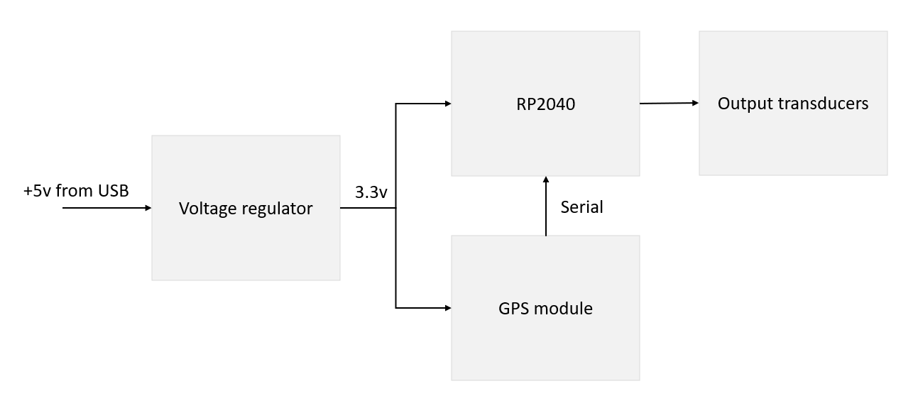
I wanted the design to be very simple: just a microprocessor, the GPS module and some RGB LEDs. Ideally I wanted to power it from USB (5V) without needing any regulators.
Here's an overview of the high level design:
Processor
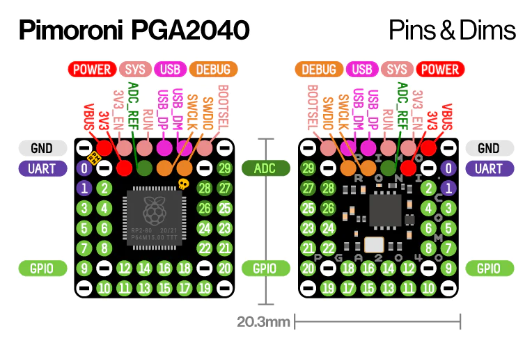
I needed something small and capable without much power draw. I'd been reading about the new(ish) Raspberry Pi RP2040 microprocessor and decided to go with this. It certainly met the capability needs (dual ARM Cortex M0+ 133MHz cores and 264kB of RAM) and was available in a lot of small packages. I chose the Pimoroni PGA2040 which packs the following into a tiny 21mm x 21mm square:
- The RP2040 chip
- 8MB flash
- 3.3v regulator
- 48 pins (of which 30 are GPIO)
It could also be powered by 5v (from USB) and provide a 3.3v output to run the GPS receiver.
The chip can be programmed using C/C++ or MicroPython and I chose C++ for this exercise. It is very easy to program, you just need to boot it into programming mode and it will mount as a USB mass storage device, allowing you to drag and drop your binary to upload it. I'll talk more about this later.
GPS Receiver
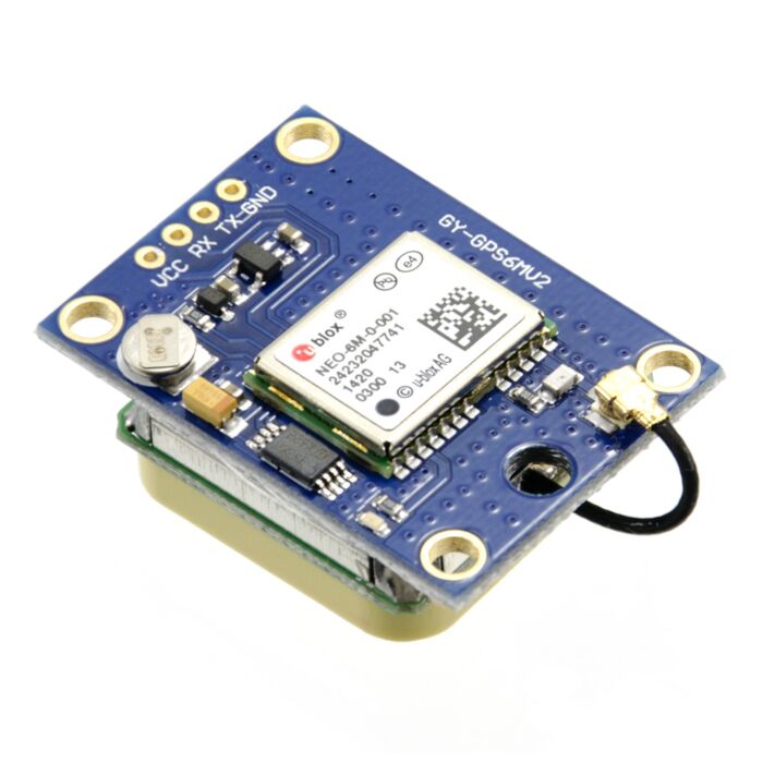
There are many such modules available, and I picked a small one made by Core Electronics based on the U-Blox NEO-6M chip. It is very simple to use, needing only 4 connections and outputs the GPS data as NMEA sentences on the serial port, which are easy to parse to get location and time data.
This small board runs on 3.3v and uses 3.3v TTL logic, so it is perfect to work with the PGA2040 board.
Output
I used simple RGB LEDs as the outputs, connecting them to the GPIO pins on the RP2040 and using PWM. The hardware PWM on the RP2040 has two channels and each channel has 8 slices, so it can drive 16 PWM outputs. Any of the 30 GPIO pins can be connected to a PWM output.
Using PWM with the RGB LED means we can generate a large number of different colours.
PWM stands for 'pulse width modulation' and I've written about it before: https://rjk.codes/post/driving-a-8x8-rgb-led-matrix-with-arduino/
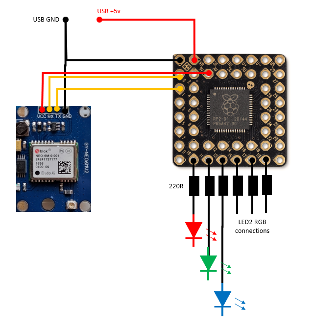
The circuit
The overall circuit was very simple, as the PGA2040 package has the onboard storage and voltage regulator, so all I needed to do was connect up a USB interface, the GPS module and the RGB LEDs with ballast resistors to protect the diodes.
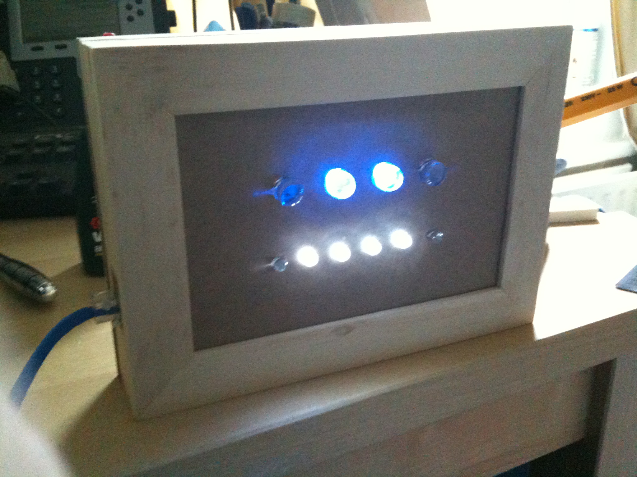
Here's a prototype of an early version on a breadboard, in this version the code is changing the colour of the RGB LED every second.
Sofware
The microprocessor needed code to run and get the time from the GPS module and then drive the LED output with PWM in a predicatble manner based on the time.
As I mentioned earlier, there is a standard for the format of information which is emitted by many GPS units called NMEA 0183 and the unit I picked uses this. So I started by building a parser for the messages which contain time information. The RMC or 'recommended minimum navigation information' message contains the time in UTC, so I used this one.
The basic code to parse this message is here https://github.com/richardjkendall/rp2040-gps/blob/main/gps.c and the method which does the work is called nmea_sentence_to_time, it accepts the NMEA sentence as an input and returns the UTC time if it is able to find it.
As the RP2040 has two cores I used one to receive and process GPS messages and the other to drive the LEDs. You can see details on how to use the second core here
| Core 0 | Core 1 |
|---|---|
|
|
Overall the code is pretty simple, it gets messages about once every second from the GPS module and extracts the time from them. It then checks what the hour is, and based on the current hour it then displays a colour pattern on the LEDs. The colour patterns are driven based on the seconds value derived from the GPS time information as well.
The colour patterns are specified in core1.c, there is one pattern for each of the 24 hours in a day and each pattern specifies a sequence of colours per LED along with a step delay (how many fractions of a second should a step last for) as well as a change 'behaviour' - which is: should the change in colour be sudden or faded? The colours themselves are specified as RGB values where full brightness is 1024 and off is 0.
You can see the full set of code here https://github.com/richardjkendall/rp2040-gps.
Enclosure
I've written in the past about my adventures with a 3d printer and this seemed like another perfect use case for it. I was not really very happy with my final product, but that's not really to do with the printer or process.
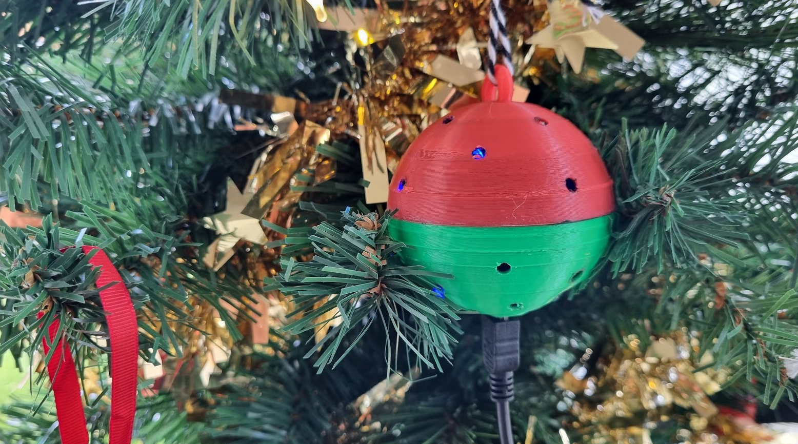
I designed the bauble using FreeCad as two hollow spheres where one of the spheres had a ring at the top which was to be used to tie on a string to hang the decoration on a tree.
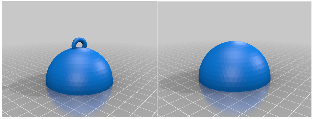
You can see the design and download the files here https://www.thingiverse.com/thing:5676095.
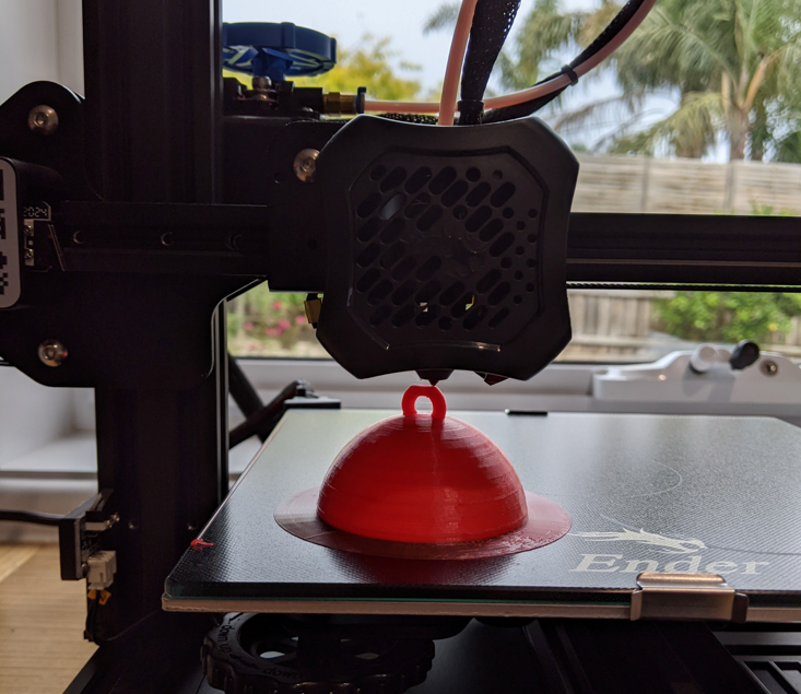
I printed the top half in red filament and the bottom in green (very festive) so that I could put the electronics inside and then glue it together. My plan was to drill a hole at the bottom for the USB connector and to drill several small holes to allow the light from the LEDs to escape.
Here's a photo of one of the bauble tops being printed:
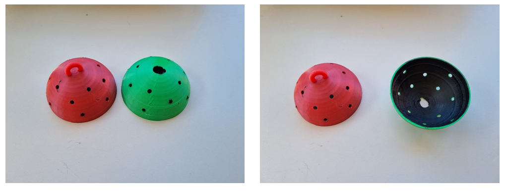
And the finished enclosures before they had anything put in them
Putting it together
At this point I had the enclosures, electronics and software, so I put it all together. I used Veroboard (stripboard) to connect the major components together (the PGA2040, USB connector, GPS module and LEDs) and made it small enough to fit inside the printed enclosure.
Here's a photo of two of the bottom halfs after the electronics had been added:
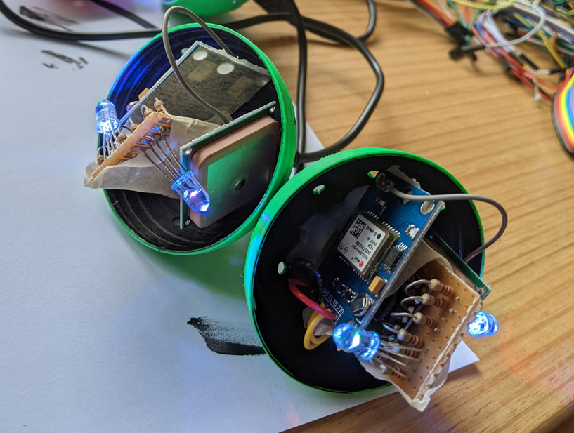
You can see here that I attached the electronics to the bauble by gluing it in with a hot glue gun. That was an error - I'm quite new to 3d printing and did not realise that 1) the PLA I was using is a themoplastic and 2) that hot glue guns are hot enough to melt PLA. It made it hard to keep their shape once I'd glued in the electronics.
I had also painted the inside of the printed parts black because I thought it would allow less light transmission. I just wanted the light to come from the holes I'd drilled rather than from the whole bauble. This did not work so well unfortunately as the LEDs are not omnidirectional sources of light, so in the end it meant that the light which is emitted is quite hard to see, especially in daylight.
Conclusion
So there you have it, a self-built Christmas ornament that no matter where it is in the world will display the same light patterns as any other.
There are certainly things I'd do differently next time - but it was a great learning experience.
Merry Christmas!!
-- Richard, Dec 2022